|
|
|

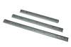
Heavy Duty Traverser Runners
A good quality runner, suitable for the larger fiddle yard.

Fitting Notes
| The load ratings are for runners that are fitted vertically & without modification (see drawing). These runners can be installed horizontally, in lighter applications, but the load capacity would be greatly reduced & they would be prone to bending. The conversion to two way operation will also decrease the load capacity. Although additional support could be provided by the use of rollers, the traverser would have to be very accurately constructed to operate smoothly. |
 |
Modifications
Do not make any modification that allows the bearing housing to be withdrawn from the outer runner. This would allow the ball bearings to fall out.
There are three possible modifications that can be made to these traverser runners:
1 Removal of Rear End Stop
At the rear end of the outer runner is a rubber end stop, this stop also provides a positive lock when in the closed position. When opening the runner, a small amount of force is needed to disengage, resulting in a sudden movement & possible derailment of any rolling stock on the traverser. Its removal is therefore advisable & easily achieved by levering upwards with a screwdriver. |

|
2 Removal of Locking Lever
The inner rail can be removed from the outer, to prevent accidental separation a release lever has to be depressed. Depending on the baseboard design, this lever my not be accessible after installing the rails, but can be removed if necccesary. It is attached to the inner rail by a single rivet, separate the rails & drill into the rivet from the outer face, the lever will then detach. |

|
3 Conversion to Two Way Operation
As manufactured, the runners will only open one way but can be modified to give two way operation, increasing the travel.
1. Firstly carry out the modifications as specified in the above two paragraphs.
2. Remove the lip from the front end of the inner rail, use a hacksaw & tidy the end with a file.

As supplied
|

Modified
|
3. On the outer rail, close to the rear end, are a pair of small tabs. These are end stops, limiting the movement of the bearing cage. They should be either removed, or flattened with the use of a hammer & pin punch.

As supplied
|

Modified
|
4. There is a plastic moulding the front end of the outer rail. This acts as both an end stop for the bearing cage & as a guide for the inner rail. As manufactured the inner rail is always engaged with this guide. After modifcation, the inner rail needs to slide out of this guide, which can foul when re-entering. By trimming the moulding as below, this problem is eliminated. While it is possible to just remove the moulding, it is not recommended, as the bearing housing could then slide out, resulting in the loss of the balls.

Remove areas coloured red
|

Modified
|
5. Reassemble the runner & check for freedom of movement.
Dimensions
| Code |
Installed Length |
Travel
(Extension)
One Way |
Travel
(Extension)
Two Way |
Dim A |
Dim B |
Maximum Load
Per Runner |
| FRH350 |
350mm |
260mm |
368mm |
N/A |
224mm |
17 kg |
|
| FRH450/1 |
450mm |
331mm |
610mm |
128mm |
224mm |
17 kg |
|
| FRH550 |
550mm |
415mm |
665mm |
224mm |
224mm |
17 kg |
|
 |
Click picture to view
|
|
Go To
Shop Listing |
See All
Items |
|
|